White Paper
ANGLELOCK® JOINT TECHNOLOGY
High Performance & Dynamic Aluminum Structure
Original: July 13, 2022 · Revised: September 15, 2026 — Carl Richter, P.E.
Dr. Horne is also an engineer at NASA. This testing was conducted independently for Controlled Dynamics and is not an official NASA evaluation or endorsement.
8,370 N
Fracture Load, Vertical
64%
Headroom Beyond Proof Load
0.035mm
Average Drift, 10 Rebuild Cycles
Key Findings
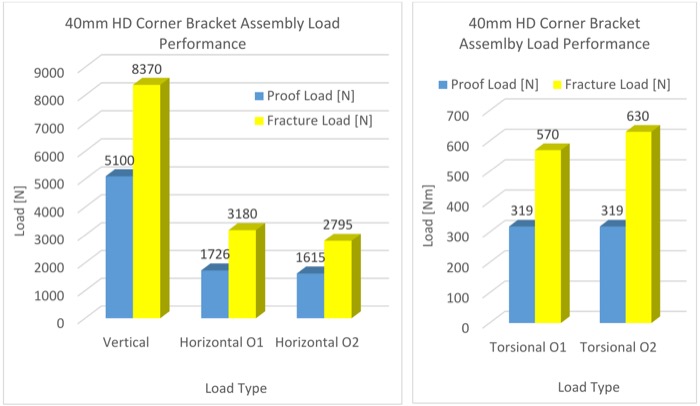
- ●The ANGLELOCK® joint sustains a static vertical proof load of approximately 5,100 N and a fracture load of 8,370 N on a 40mm Heavy Duty Corner Bracket.
- ●Horizontal proof loads measured 1,726 N (Orientation 1) and 1,615 N (Orientation 2), with fracture loads of 3,180 N and 2,795 N.
- ●Torsional proof load reached 319 N·m in both bracket orientations, with fracture loads of 570 N·m and 630 N·m.
- ●Moment (bending) proof loads ranged from 480 N·m to 1,800 N·m depending on orientation, with fracture loads up to 3,690 N·m.
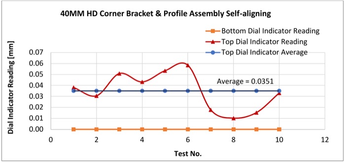
- ●Across 10 full disassembly/reassembly cycles, the joint realigned to within an average of 0.035 mm — with no squares or alignment tools used.
- ●This paper's analytical rail proof moment of 1,710 N·m agrees within 1% with the 1,695 N·m independently reported in David Gerow, P.E.'s companion finite-element analysis of the same rail and bracket.
The Problem
T-slot aluminum framing has been in the market since 1975. It's modular, affordable, and easy to reconfigure — but the traditional T-nut connector relies on frictional force between flat contact planes. Under dynamic load, that pivot point allows slippage and misalignment, loosening the fastener over time. Designers have added gussets and stiffer T-nuts to compensate, but the underlying weak link — friction instead of a mechanical lock — remained.
How ANGLELOCK® Works
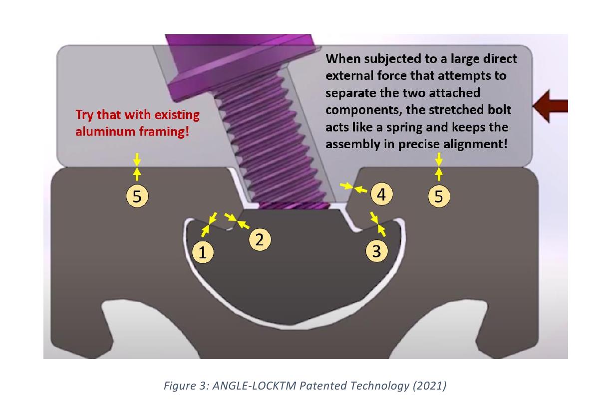
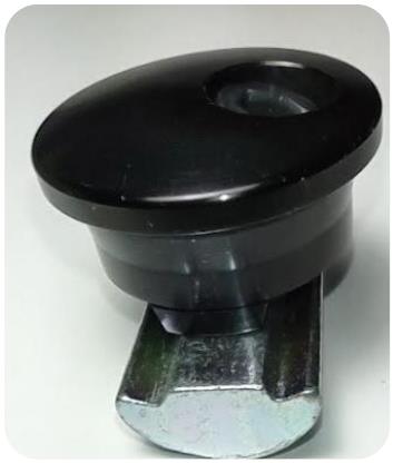
The ANGLELOCK® nut has three angled surfaces that meet matching angled surfaces machined into the aluminum extrusion. As the fastener is tightened, the nut rotates and anchors itself across five separate contact planes — not one flat frictional plane. The stretched bolt acts like a spring, pulling the entire assembly into alignment rather than allowing it to loosen. Unlike the traditional T-slot, where friction and pivoting cause fasteners to work loose, the ANGLELOCK® design pulls tighter as load is applied.
Test Methodology
Testing used the 40mm Heavy Duty Corner Bracket mounted on Controlled Dynamics' 40x40 4-Slot High-Definition extrusion, fastened to a hole-patterned plate and mounted on an Instron testing machine. Three specimens were tested in each configuration, with all bolts torqued to 20.33 N·m for repeatability. Proof load — the limit of the bolt's elastic range — was conservatively set at 85% of yield strength, in line with standard industry practice. Fracture loads were read directly from the test curves.
Test Results
| Test Mode | Proof Load | Fracture Load |
|---|---|---|
| Vertical Loading Bracket mounted to vertical profile with downward load applied at 250mm from the base — the most common installation orientation. | 5,100 N | 8,370 N |
| Horizontal Loading — Orientation 1 Bracket on its side, bolt heads angled below horizontal, side load applied at 250mm from the base. | 1,726 N | 3,180 N |
| Horizontal Loading — Orientation 2 Bracket on its side, bolt heads angled above horizontal, side load applied at 250mm from the base. | 1,615 N | 2,795 N |
| Torsional Loading — Orientation 1 Pure moment about the Z-axis parallel with the free profile. | 319 N·m | 570 N·m |
| Torsional Loading — Orientation 2 Pure moment about the Z-axis, opposite rotational direction. | 319 N·m | 630 N·m |
| Moment — Vertical Closing Two-bracket I-shaped assembly, brackets mounted above the extrusion. | 1,800 N·m | 3,000 N·m |
| Moment — Vertical Opening Same assembly, brackets mounted below the extrusion. | 3,000 N·m | 3,690 N·m |
| Moment — Horizontal Orientation 1 Two-bracket assembly rotated 90° into horizontal loading. | 480 N·m | 500 N·m |
| Moment — Horizontal Orientation 2 Same horizontal assembly, opposite bracket orientation. | 2,260 N·m | 960 N·m |
Tensile proof/fracture figures for the bracket assembly were not isolated in this paper; see the full PDF for the 40x40 4-Slot HD extrusion's tensile, shear, and torque analysis (228,071 N tensile fracture load, analytically derived).
Self-Aligning Assembly
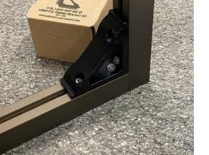
A 40mm Heavy Duty Corner Bracket connection was fully disassembled and reassembled 10 times, with profile deviation from vertical measured after each cycle. No squares or alignment tools were used, to emulate a real assembly scenario. The average deviation across all 10 cycles was 0.035 mm — demonstrating that the mechanical lock realigns the joint to the same position every time, rather than drifting with repeated use.
Independent Cross-Validation
This paper's analytical rail proof moment of 1,710 N·m agrees within 1% with the 1,695 N·m independently reported in David Gerow, P.E.'s companion white paper, “AngleLock Framing Can Be Analyzed with Beam-Element FEA,” which tests the same 40×40 mm 4-Slot HD rail and heavy-duty corner bracket using its own finite element methodology. Gerow's reported bracket moment capacity of approximately 2,900 N·m also falls within the joint proof-to-fracture range measured here for the vertical orientations (1,800–3,690 N·m). Because both papers rely on the same underlying components but reach their numbers independently, the agreement corroborates both data sets.
Conclusion
Controlled Dynamics designed the ANGLELOCK® joint to eliminate the frictional pivot point responsible for fastener loosening in traditional T-slot aluminum framing. Testing across five load modes — vertical, horizontal, tensile, torsional, and moment — on the 40mm Heavy Duty Corner Bracket confirms a mechanical lock that holds its proof load, self-aligns on reassembly, and matches an independently derived finite-element analysis of the same components within 1%.
Test data and analysis in the full paper illustrate the performance of the CDI 40mm Corner Bracket assembly specifically and is not intended as a general bracket load reference. Customers should conduct their own testing and analysis for their specific assembly load and configuration.